

It has high brightness, long lifetime and good uniformity features CCFL frequently employs fluorescent lamps, which have a phosphorcoated glass cylinder with cathodes at each end.. It can also be drive bigger size LED screens, too LCD TV applications can be used in a variety of architecture produced the AC waveform required to drive CCFL, CCFL drive more when faced three key challenges is to select the best design-driven architecture, multi-lamp drivers, lamp dimming frequency and TLP620-2 datasheet and pulse frequency control.. LED Drivers: MS456UB - 59 99 THyperLink his is a custom design for all UB Series LED kit.
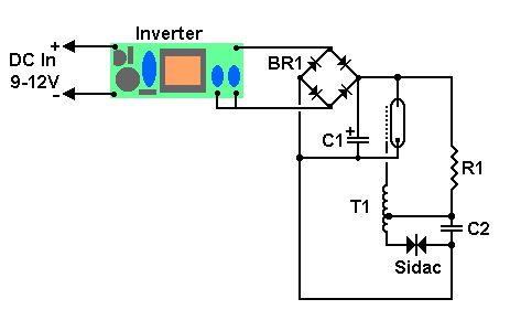
In this paper, four common driver architecture has been analyzed and TLP620-2 price and proposed to solve multi-lamp design.. Always try to keep the test time as short as possible Warning Repairing the LCD backlight unit is not an easy task even for experienced technicians.. Assemble the circuit on a generalpurpose PCB and enclose in a suitable cabinet Fix the 2-pin connector on front side of the cabinet in such a way that the CCFL under test can easily be connected here.. Here an ordinary step-down transformer is used as the inverter transformer by reversing its primary and secondary windings.
ccfl driver circuit
ccfl driver circuit, ccfl backlight driver circuit, ccfl lamp driver circuit, cfl driver circuit, cfl driver circuit diagram, ccfl driver schematic, ccfl driver ic Download Gratis Film Kartun Marsha And The Bear
If you do something wrong you may permanently damage the LCD screen and have to buy a new one!Ccfl driver schematic datasheet, cross reference, circuit and application notes in pdf format.. LCD backlight mainly consists of a light source, diaphragm, light-leading board and plastic frame.. var q = 'ccfl%20driver%20circuit'; Liquid crystal displays (LCDs) are used in a wide range of products including flat-screen computer monitors, laptop computers,tablet PCs, PDAs, digital cameras and portable instruments, compact cold cathode fluorescent lamp (CCFL)-based backlight (illumination source for the LCD screen) arrangement in these applications enables a wellviewable display in both dim and bright ambient light conditions.. CCFL tube is powered by a small electronic inverter (CCFL inverter) circuit that glows the screen electronically.. If the CCFL is good, you will notice a dim/bright glow in it (depends on the wattage rating of the CCFL under test). Und Gamepad-PC

ccfl lamp driver circuit
cfl driver circuit diagram

This basic circuit (go/no go test) is portable, 6V battery operated and can be used to test almost all types of LCD backlight CCFL tubes.. Fix the test switch on top of the frame Keep the 6V battery in side the cabinet.. Components R2, R3 and C3 determine the operating frequency of the AMV MOSFET T1 switches the inverter output transformer (X1) to produce high-voltage AC supply at its output terminals. 518b7cbc7d
0